Vertical Antenna Ground Radial Loss Study
This document examines three published ground radial loss studies
along with limited empirical data collected as a sanity test.
ARRL Antenna Book Ground Radial Loss
The ARRL Antenna Books use ground loss data compiled by John
Stanley, K4ERO, using information from the book, Radio Broadcast
Ground Systems, 1972, and first presented in the December, 1976,
QST. The data in Table 1 is from two editions
of the ARRL Antenna Book and are joined, at 36 radials. A 0.08
dB loss is added to merge with EZNEC data.
- 15th Edition ARRL Antenna Book, Page 3-13, Table 3
- 22nd Edition ARRL Antenna Book, Page 3-14, Figure 3.27
| Table 1 - ARRL Antenna
Book Radial Loss
|
|---|
| Radials | Loss dB | Loss dB
1.79 dBi Ref | Radial
Wavelength | Reference
|
|---|
| 120 | 0.0 | 0.08 | 0.4 | Table 3
| | 90 | 0.5 | 0.58 | 0.25 | Table 3
| | 60 | 1.0 | 1.08 | 0.2 | Table 3
| | 36 | 1.5 | 1.58 |
| Figure 3.27
| | 36 | 1.5 | 1.58 | 0.15 | Table 3
| | 24 | 2.0 | 2.08 |
| Figure 3.27
| | 24 | 2.0 | 2.08 | 0.125 | Table 3
| | 16 | 2.9 | 2.98 |
| Figure 3.27
| | 16 | 3.0 | 3.08 | 0.1 | Table 3
| | 8 | 5.0 | 5.08 |
| Figure 3.27
| | 4 | 7.0 | 7.08 |
| Figure 3.27
|
|
K3LC EZNEC4 Models
Al Christman, K3LC, used EZNEC4 to model a variety of radial ground
systems. The results are published in the document
Maximum-Gain
Radial Ground Systems for Vertical Antennas, 2004.
Table 2 and Table 3 are
loss data for 40 and 160 Meter vertical antennas over average soil.
The data is normalized to a 1.79 dBi zero ground loss vertical
antenna.
| Table 2 - K3LC Table I, 40 Meter Vertical
Antenna Over Average Soil
|
|---|
| Radials | Peak Gain dBi | Loss dB
1.79 dBi Ref | Radial
Wavelength
|
|---|
| 102 | 1.40 | 0.39 | 0.57
| | 63 | 0.90 | 0.89 | 0.47
| | 42 | 0.33 | 1.46 | 0.36
| | 30 | -0.22 | 2.01 | 0.25
| | 22 | -0.67 | 2.46 | 0.17
| | 14 | -1.07 | 2.86 | 0.13
| | 9 | -1.49 | 3.28 | 0.10
|
|
| Table 3 - K3LC Table VII,
160 Meter Vertical
Antenna Over Average Soil
|
|---|
| Radials | Peak Gain dBi | Loss dB
1.79 dBi Ref | Radial
Wavelength
|
|---|
| 111 | 1.75 | 0.04 | 0.55
| | 76 | 1.48 | 0.31 | 0.39
| | 50 | 1.17 | 0.62 | 0.30
| | 36 | 0.89 | 0.9 | 0.21
| | 26 | 0.63 | 1.16 | 0.15
| | 18 | 0.38 | 1.41 | 0.11
| | 12 | 0.11 | 1.68 | 0.08
|
|
N6LF Vertical Antenna Ground Systems
Rudy Severns, N6LF, revisited previous studies and published his
results in
Vertical Antenna Ground Systems At HF. The results for 160 Meters
over average ground are summarized in Table 4.
| Table 4 - N6LF Figure 15
Antenna Over Average Soil
|
|---|
| Radials | Peak Gain dBi | Loss dB
1.79 dBi Ref
|
|---|
| 128 | 1.75 | 0.04
| | 64 | 1.45 | 0.34
| | 32 | 1.05 | 0.74
| | 16 | 0.6 | 1.19
| | 8 | 0.0 | 1.79
| | 4 | -0.7 | 2.49
|
|
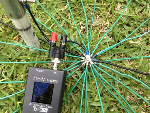
KN5L 20 Meter Vertical Measurements
A 20 meter vertical consisting of 8" #14 wire and 16.5'x1" aluminum
pole was measured against three sets of ground radials is shown in Figure 1.
Measurements were taken at the antenna using a
FG-01 Antenna Analyzer.
EZNEC is used to solve the ground
loss by adding load resistance such that the model matches the antenna
measured impedance. The EZNEC 2D plot is used to evaluate antenna
loss. The results are summarized in Table 5.
| Table 5 - KN5L Measurements
|
|---|
| Radials | FG-01
Measured Z | EZNEC
Added R | EZNEC
Gain dBi | Loss dB
1.79 dBi Ref
|
|---|
| Reference | NA | 0 | 1.79 | 0
| | 25 | 47 | 15 | 0.1 | 1.69
| | 20 | 50 | 18 | -0.17 | 1.96
| | 16 | 56 | 24 | -0.66 | 2.45
|
|
| Figure 1 - KN5L
20 Meter Vertical Antenna Ground Radials
|
|---|
|
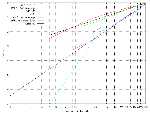
Evaluating Ground Loss Data
The graph in Figure 2 plots the four sets
of ground loss data. The ARRL Antenna Book and K3LC 40 Meter plots
have a close match from 24 to 100 radials. The ARRL data below 24
radials is suspect. The K3LC 160 Meter and N6LF plots are a close
match. The KN5L empirical data is reasonably close to the ARRL and
K3LC published data. Two "LINE" lines are added as a guide for
average 40 and 160 Meter ground radials.
Ground Loss Values
The two "LINE" lines in the above plot can be used to compute
ground loss values, summarized in Table 6 and
Table 7, for use in EZNEC
modeling using the directions in the
EZNEC manual
in the section beginning with:
- The third approach is to use
MININEC-type ground, which models the ground reflection but not the
conductive loss, and simply add a resistive load at the feedpoint to
simulate the radial system loss resistance.
| Table 6 - 160 Meter Ground Loss
|
|---|
| Radials | Loss dB | Ground Loss Ohms
|
|---|
| 120 | 0.0 | 0.2
| | 60 | 0.5 | 3.7
| | 32 | 0.8 | 7.2
| | 24 | 1.1 | 8.9
| | 16 | 1.3 | 11
| | 8 | 1.8 | 16
|
|
| Table 7 - 40 Meter Ground Loss
|
|---|
| Radials | Loss dB | Ground Loss Ohms
|
|---|
| 120 | 0.1 | 0.6
| | 60 | 1.0 | 8.2
| | 32 | 1.8 | 17
| | 24 | 2.2 | 21
| | 16 | 2.8 | 28
| | 8 | 3.7 | 42
| | 1 | 6.4 | 104
|
|
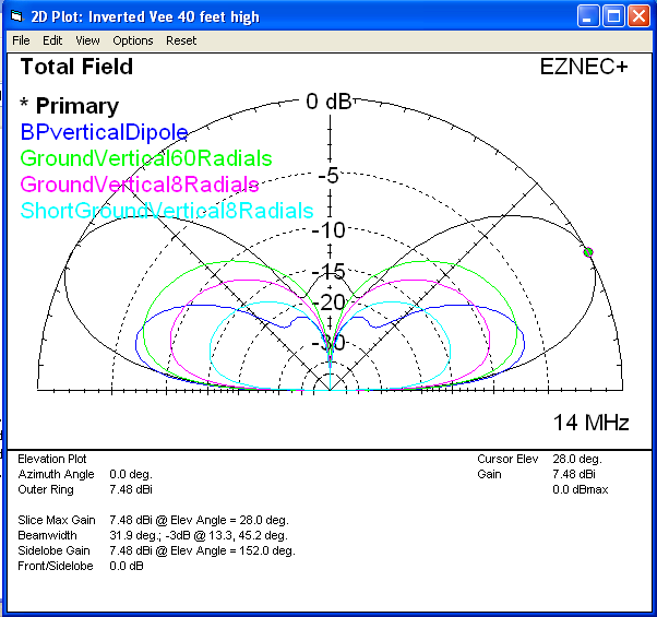
EZNEC Antenna Evaluation
The EZNEC 2D Plot below evaluates five 20 Meter antennas is shown
in Figure 3. All models use the same MININEC-type ground.
- Primary: Inverted Vee at 40 feet elevation.
- BPverticalDipole: Vertical base at 19 feet, Buddipole: 2 x
22" arms, coil 1.6 uH, and 9.5' whip with four 1/4 wave Radials at
45 degree downwards slope.
- GroundVertical60Radials: Ground mounted 1/4 wavelength
vertical with 60 on ground radials. 8.2 Ohm ground loss.
- GroundVertical8Radials: Ground mounted 1/4 wavelength vertical with
eight on ground radials. 42 Ohm ground loss.
- ShortGroundVertical8Radials: Ground mounted 0.1 wavelength vertical with
center loading and eight on ground radials. 42 Ohm ground loss.
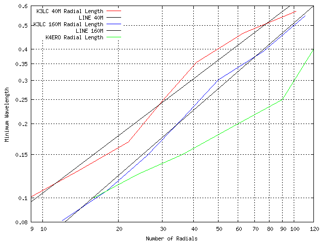
Ground Radial Length
The minimum ground radial wavelengths suggested by K4ERO and K3LC are plotted in
Figure 4.
Copyright 2013 John Oppenheimer KN5L