|
Several steps were performed for selecting the
transformer Balun. The terminated line Smith Chart was as an
indication of proper operation. With the window line directly
connected to the 50 Ohm unbalanced calibrated plane, the smith chart
had ovals with about a 2x1 shape factor. Added six inches of 43
material snap-its changed the oval shape, but still an oval.
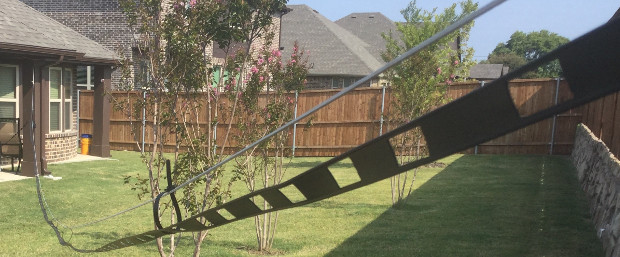
Window line, being symmetrically balanced, is a good
candidate for a transformer Balun with a grounded center tap. This
type of Balun has negligible common mode rejection. A symmetrically balanced
load has negligible common mode current.
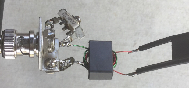
The transformer inner windings are 11T red color
#24, with a center tap. Care was taken to layer the windings. The
outer winding, four turns #22 green, is a single layer. S11
measurement with an appropriate load indicated no resonant issues.
The trace was rather flat, but decided to add the small capacitor to
compensate out leakage inductance. The range of the vintage 422 ARCO
is 40 pF. The capacitor was adjusted for a near flat response from 3
to 40 MHz. The leakage inductance takes over above 40 MHz. Below 3
MHz suffers from low winding inductance. Suspect the capacitor to be
at about 30 pF.
OSL calibration was performed at the 11T solder
connections. The load is a VNWA measured 390 Ohm 1/4 watt
beige-bodied, probably helical cut carbon film, which measured 380 Ohm
with an inductance of 30 nH. The resistor values entered into the
VNWA calibration kit window.
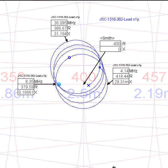
The resulting smith chart above has nice circles,
though they do spiral up a little. This is a good indication that the
selected Balun is performing the intended function.
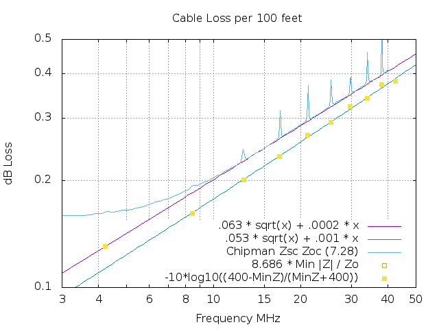
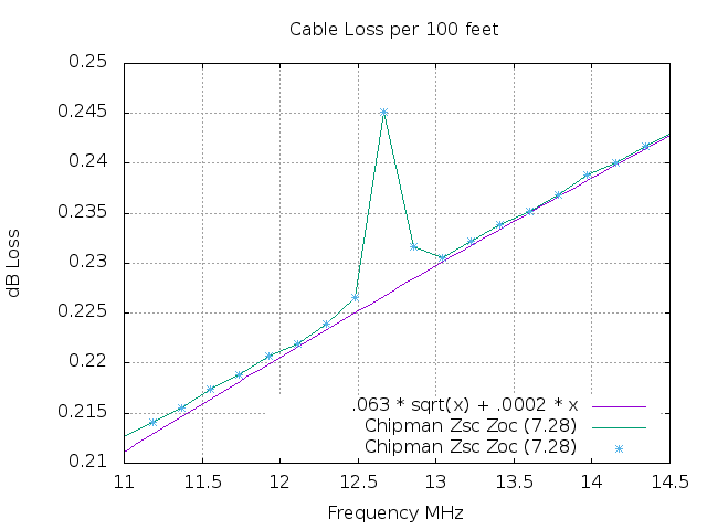
Correctness can also be evaluated by observing the
loss computations. As long as copper skin is fully involved, TL loss
will follow a k1*sqrt(F) + k2*F line. Notice in the top loss plot
that at other then the 1/4 and 1/2 wavelengths, the 10 to 40 MHz plot
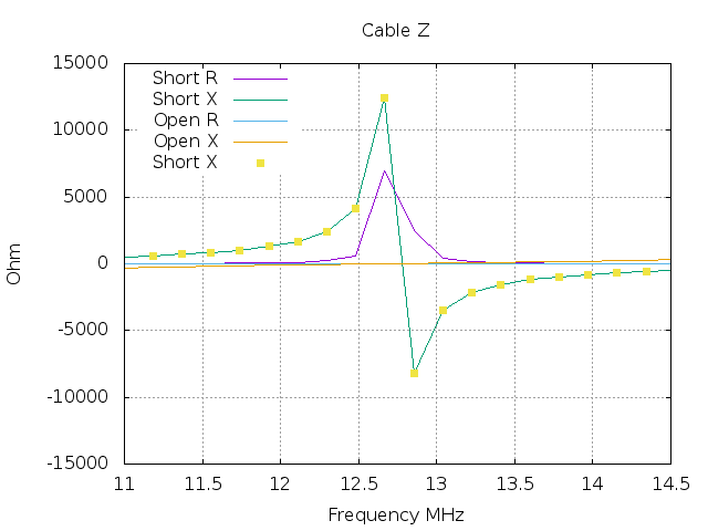
follows a k1 k2 line very nicely. The 11 to 14.5 MHz loss plot
includes marked measurement points. Other then the three points about
12.7 MHz, 3/4 wavelength, the measurements are very close to the k1 k2
line.
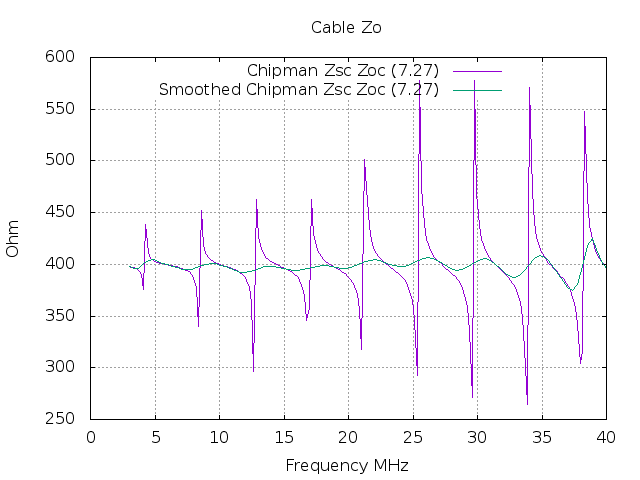
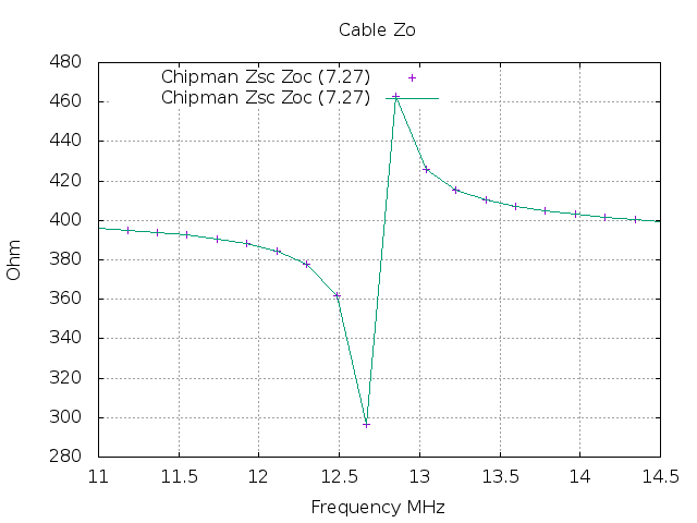
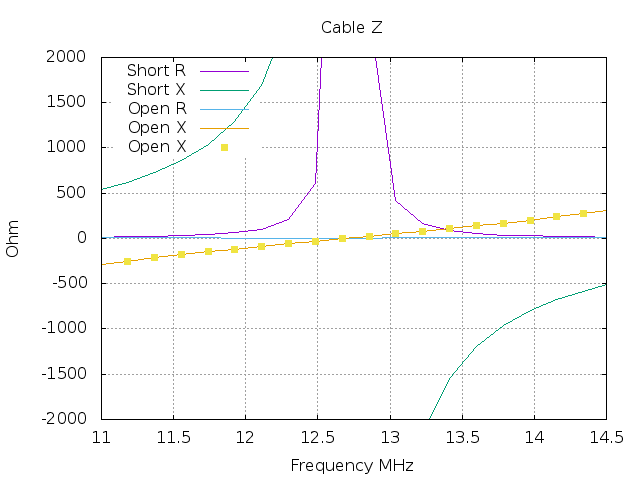
Chipman computations are not valid at Z equal zero
conditions. The detailed Zo and Loss plots centered at the 3/4
wavelength, 12.7 MHz, demonstrate the resulting values are
invalid near zero Z values.
|