| 
| |
| ||
| ||
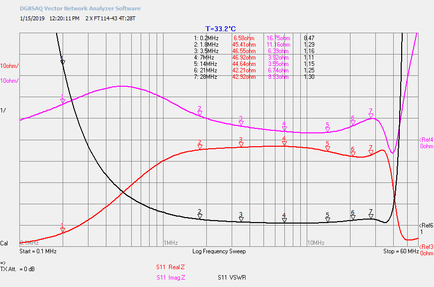
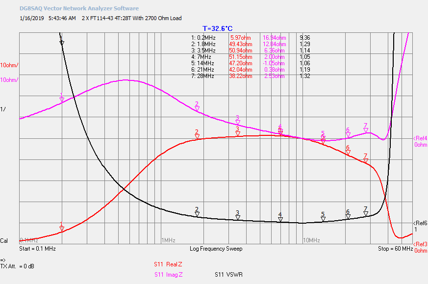
2 X FT114-43 4T:28T #22 - 49:1 Z Ratio
2450Ω Load
2700Ω Load
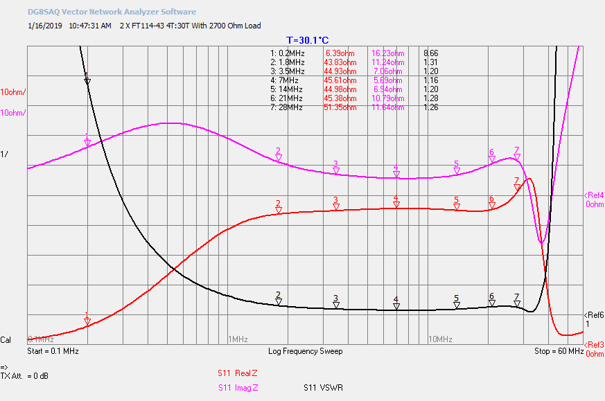
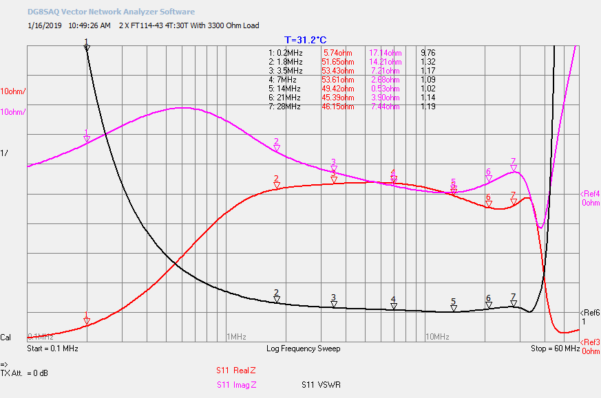
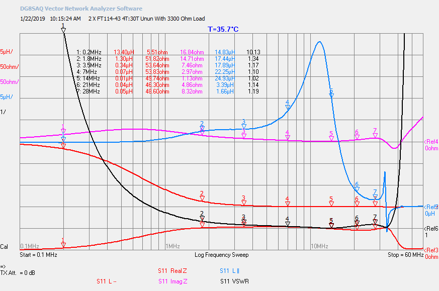
2 X FT114-43 4T:30T #22 - 56:1 Z Ratio
2700Ω Load
3300Ω Load
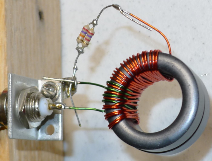
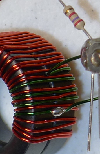
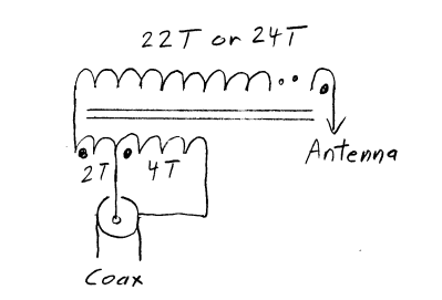
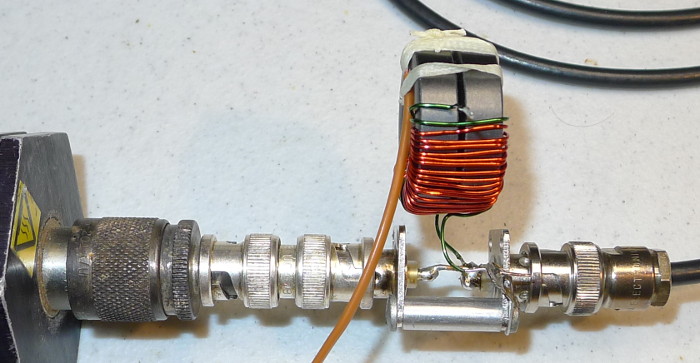
Winding Instructions
|
Optimized winding technique results with winding capacitance and leakage inductance canceling out. Referring to the photographs above. Wind the four turn primary/secondary winding. Green wire in the photograph. Each wrap through the core equal one turn. Solder the secondary wire to the primary/secondary wire. Red wire in the photograph. This will be the primary tap which is connected to the 50Ω transmission line center conductor. Wind two turns of the secondary in the same direction as the primary/secondary turns. Wind the secondary over the initial six turns. Crossing over the windings inside the core forming a winding per winding interlace. Wind on six interlaces turns. Continue winding the secondary windings to the desired turn count. |
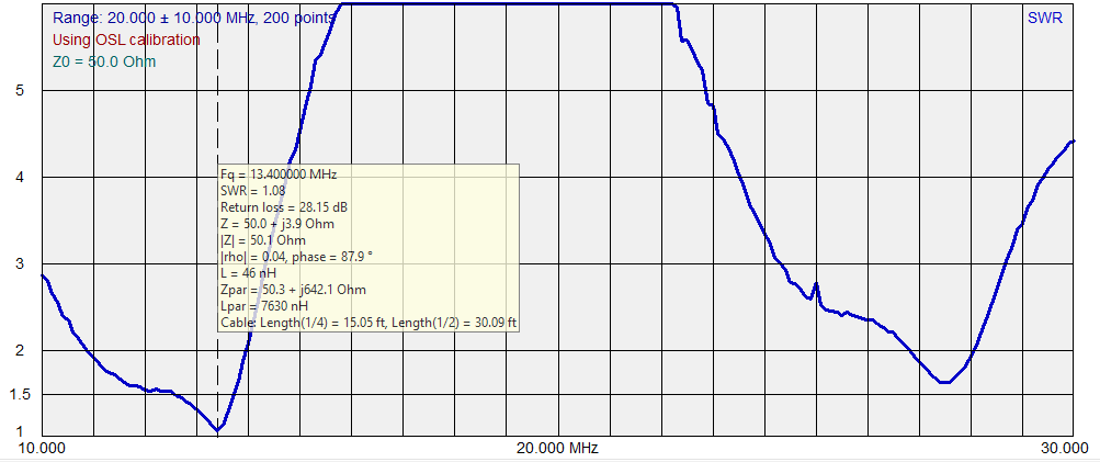
Antenna Measurement
| |
|
Temperature Rise Measurement
|
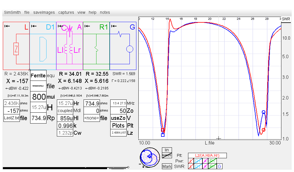
Series and Parallel Inductance Measurement
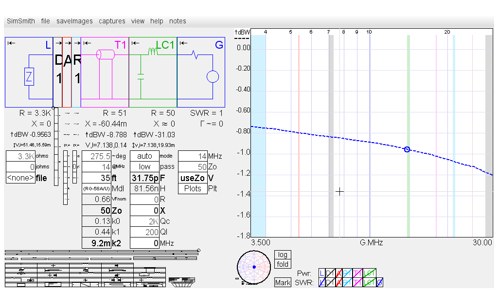
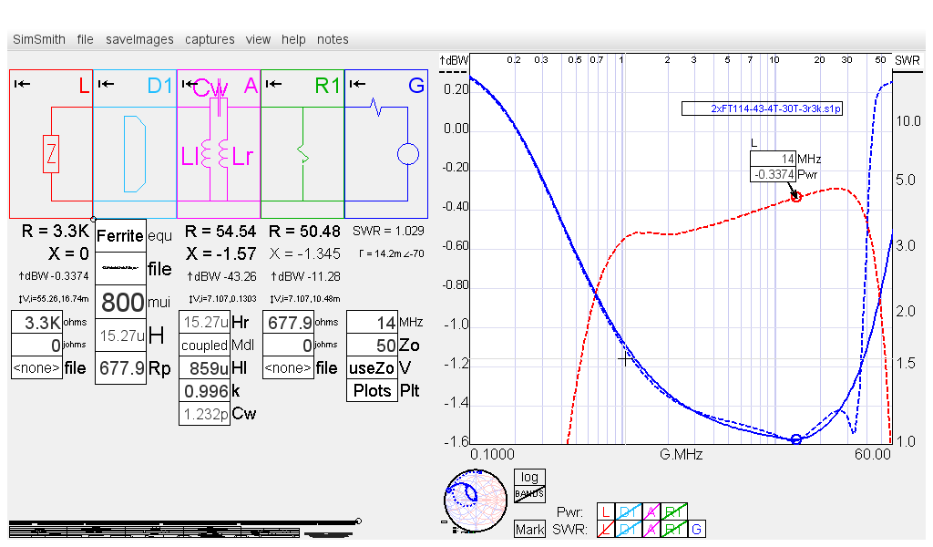
2 X FT114-43 4T:30T 3300Ω Load SimSmith Approximation
SS R1.ohms adjusted for -0.3 dB at 14 MHz
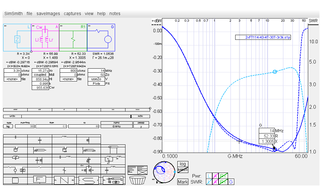
2 X FT114-43 4T:30T 3300Ω Load SimSmith Approximation
With Fair-Rite Complex Permeability Model
|
| D1 Text for Cut and Paste |
|---|
//Ferrite $data=file[]; //SS Fair-Rite permeability file mui;H; $mup = $data.R; $mupp = $data.X; $Ls = H * ($mup/mui); $Xs = 2*Pi * G.MHz * 1M * $Ls; $Q = $mup / $mupp; $Rs = $Xs / $Q; Rp = ($Q^2 + 1) * $Rs; A.Hr = H; R1.ohms= Rp; |
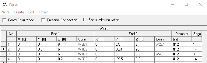
EZNEC and SimSmith Models
Source connected to Wire 1
Unun + 35' RG-58A/U + Antenna Tuner System Loss Analysis