RG174 25' 1:4 TLT with 1N34A RF Volt Meter
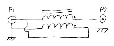
1:4 TLT DUT and Fixture Schematic
| SimSmith; Model, VNWA S21dB, and RF Volt Meter Results |
|---|
|
Through DUT for Calibration
1:4 TLT DUT and Fixture Schematic
| SimSmith; Model, VNWA S21dB, and RF Volt Meter Results |
|---|
|
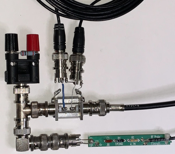
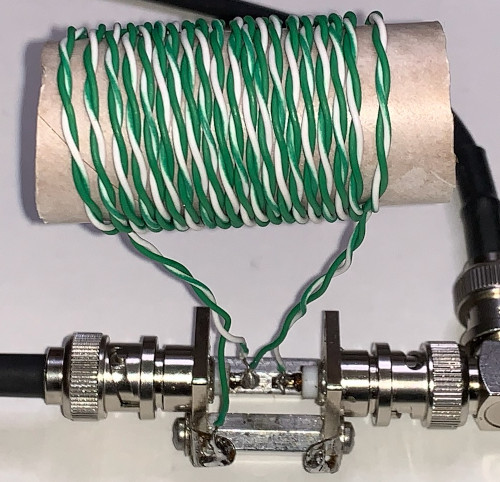
Preferred approach for demonstrating Transmission Line Transformer (TLT) Transmission Line Mode (also referred to as TEM ) is a purpose made TLT such that S21 dB includes leading edge of shunt inductance R,L High Pass Filter (HPF) and 1st and 3rd 1/2 wavelength multiples Insertion Loss (IL) nulls. To minimize frequency range, use a low inductance TLT with a long transmission line. For 3rd IL null below 200MHz, 70 inch 100Ω nominal 70% Vf TL is selected. TL is wound onto a 1" form using 20 turns. CAT-6 twisted pair is used. 70in includes two 2" pigtails. Fixture includes 150Ω load resistor for matching to 50Ω VNA Port-2. Load resistor results with 6dB measurement loss.
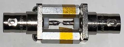
1:4 TLT and Fixture
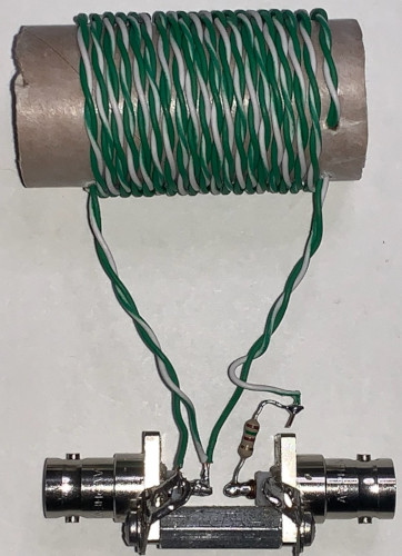
1:4 TLT and Fixture Schematic

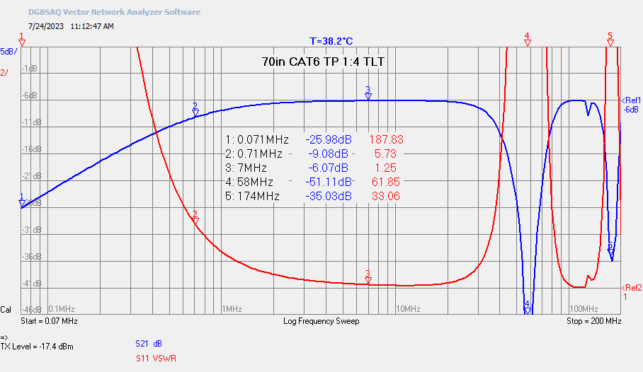
Selecting start frequency such that measured HPF S21 is -20dB, one decade below HPF resonant frequency. TLT, as an inductor, L=5.6uH. Resonant frequency, f = 25 / (2 * Pi * 5.6u) = 710kHz. One decade down, for -20dB, 71kHz. VNWA sweep set to 70kHz to 200MHz.
Note resonant frequency, 710kHz is 3dB down. 71kHz is 20dB down. 1st and 3rd 1/2 wavelength IL nulls are 58MHz and 174MHz
1:4 TLT VNWA Results
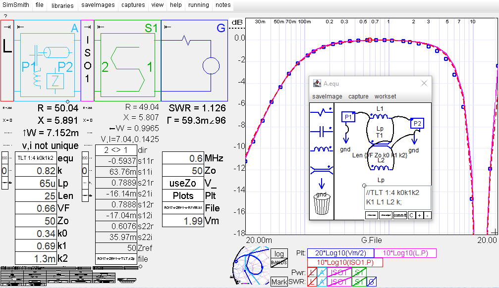
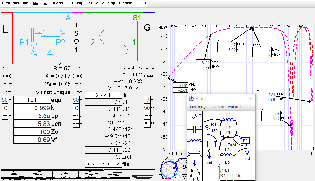
Above VNWA S2P file exported to SimSmith for analysis. Matching TLT model with TL length set to 70" and Lp set to 5.6uH. Model Vf is tuned, 0.69, such that measurement and model 1st and 3rd frequencies match. 69% velocity factor is well within expectation for Cat-6 twisted pair. SimSmith files: ss-TLT-70in-CAT6.zip
1:4 TLT SimSmith Results
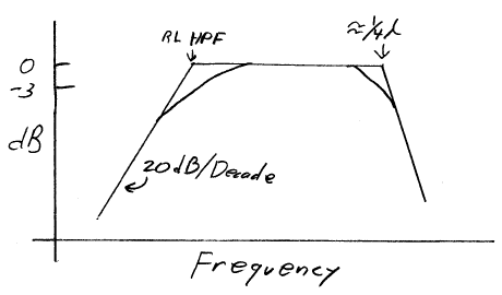
Evaluating initial VNWA S21 dB trace, -3dB High Frequency bandwidth is approximately 1/4 TL Wavelength, about 30MHz for measured TLT. Low frequency -3dB bandwidth is a function of choking inductance HPF resonant frequency. Therefore quite simple to make a 3dB Bandwidth Bode Plot, example:
1:4 TLT Bode Plot
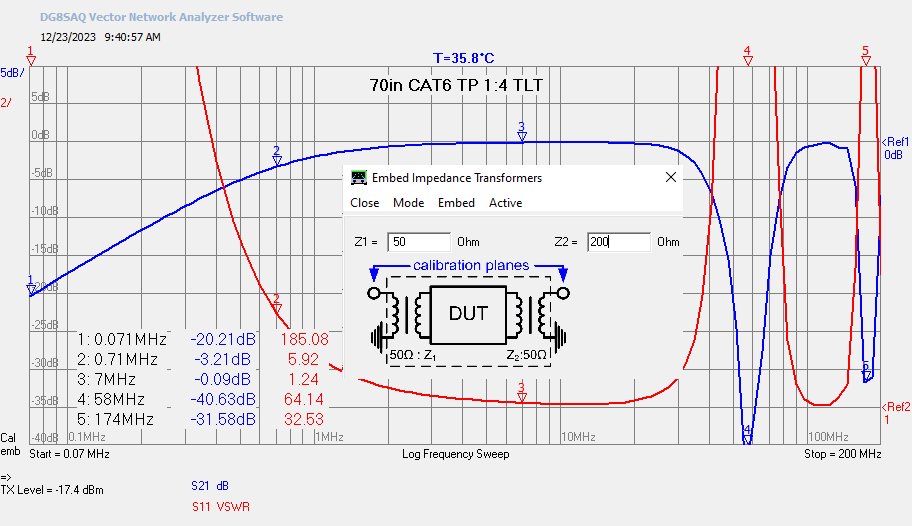
VNWA 50Ω - 50Ω 12-term Correction Measurement
VNWA DUT measurement using a fixture without a 150Ω Port-2 matching resistor. 12-term correction measurement. Using VNWA builtin Embed Impedance Transformer to transform VNWA 50Ω - 50Ω S2P measurement to 50Ω - 200Ω measurement evaluation.