Q Meter Study
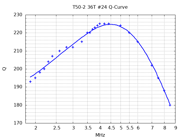
T50-2 36T #24 Q-Curve Measurement
|
Q-Capacitor Prototype
|
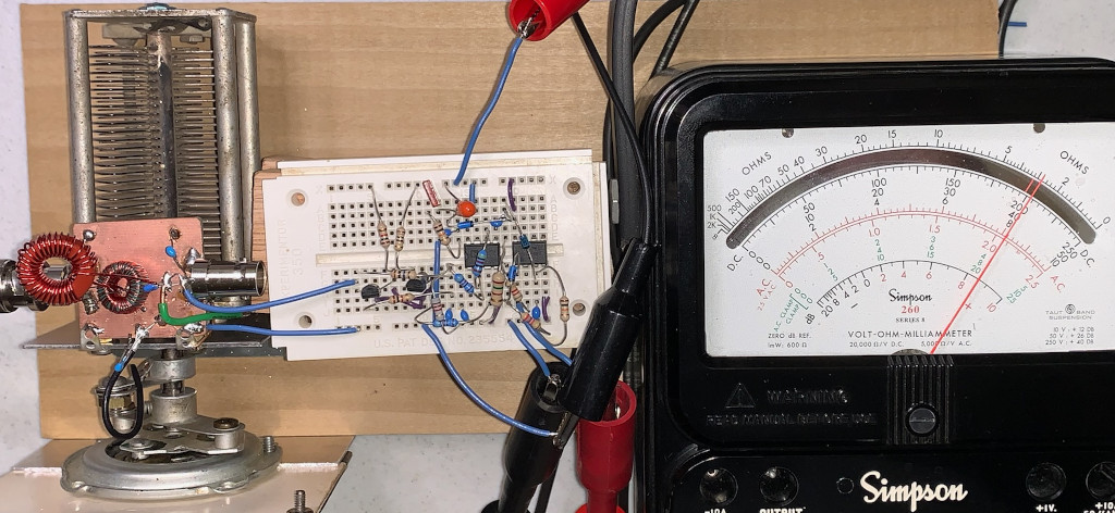
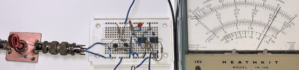
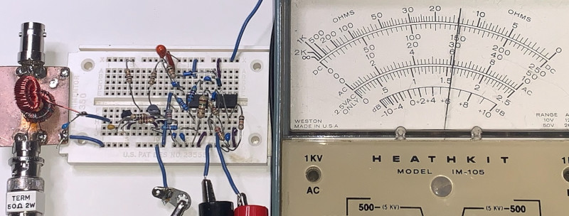
Q-Meter Prototype
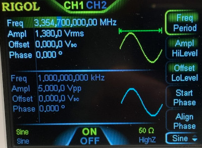
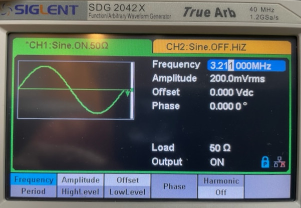
DG1032 AWG Settings
Q Meter Measurement
|
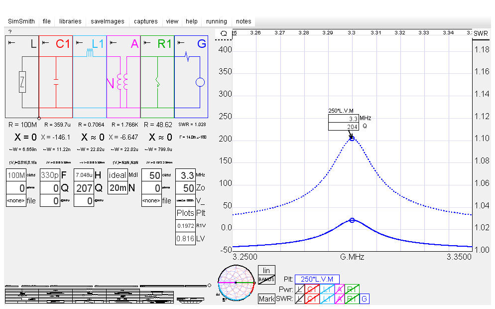
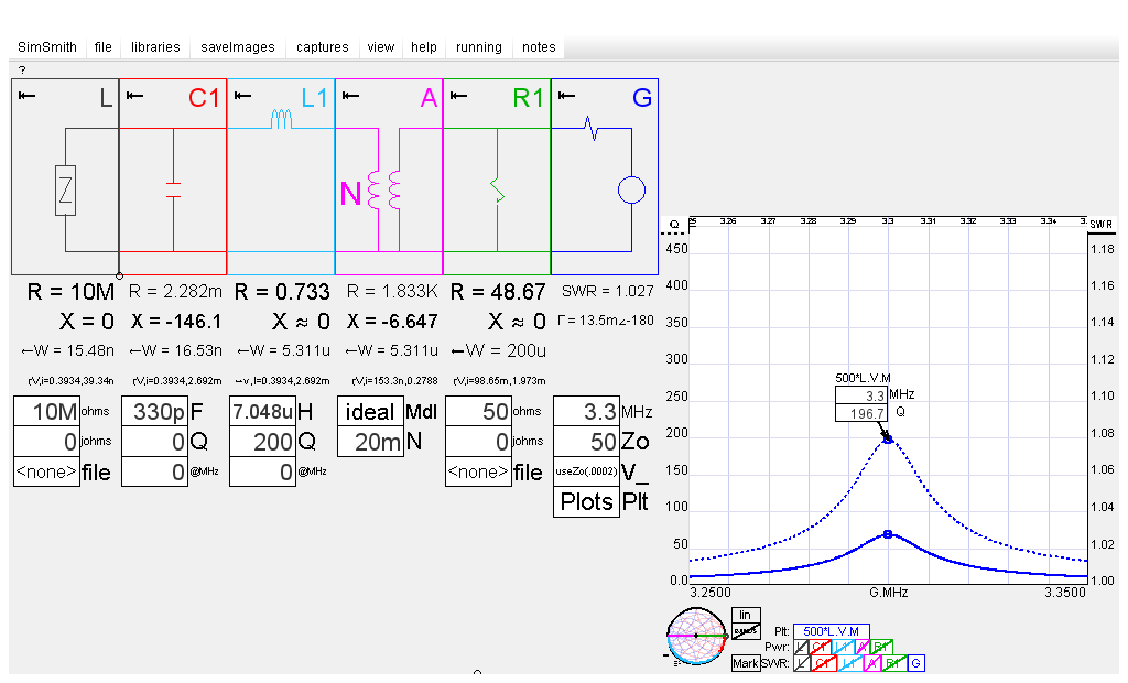
SimSmith Model with DUT Q=207
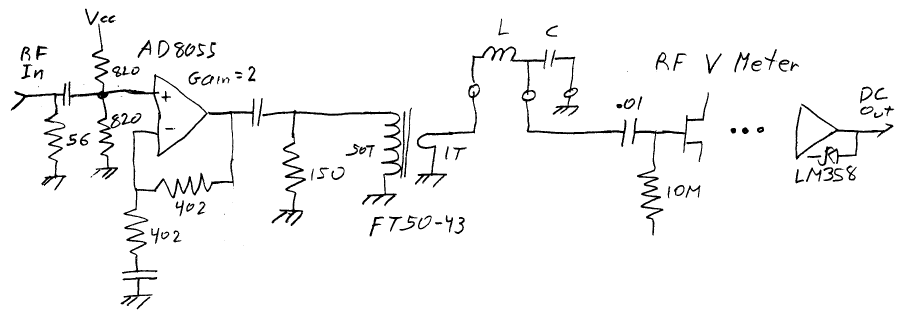
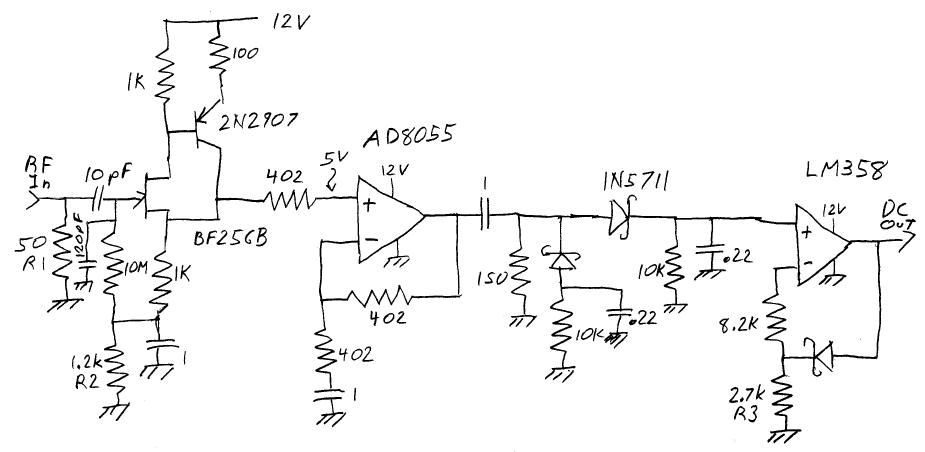
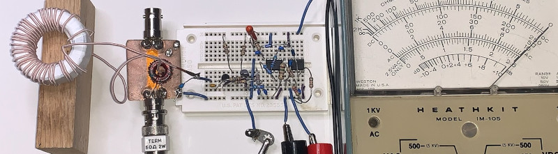
Injection Transformer Fixture Schematic
![]()
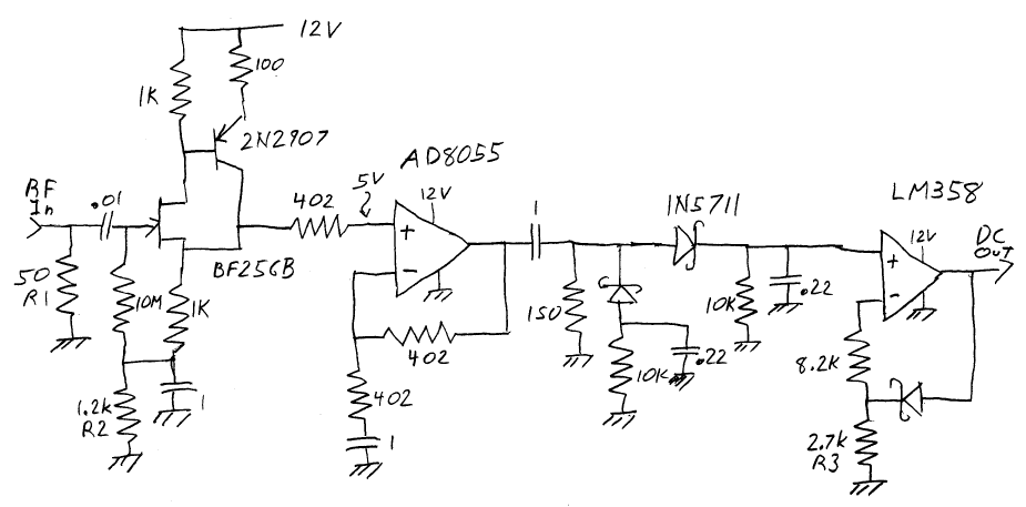
RF Voltmeter Prototype
Schematic
|
Injection Transformer, With Capacitive Divider, Fixture
![]()
![]()
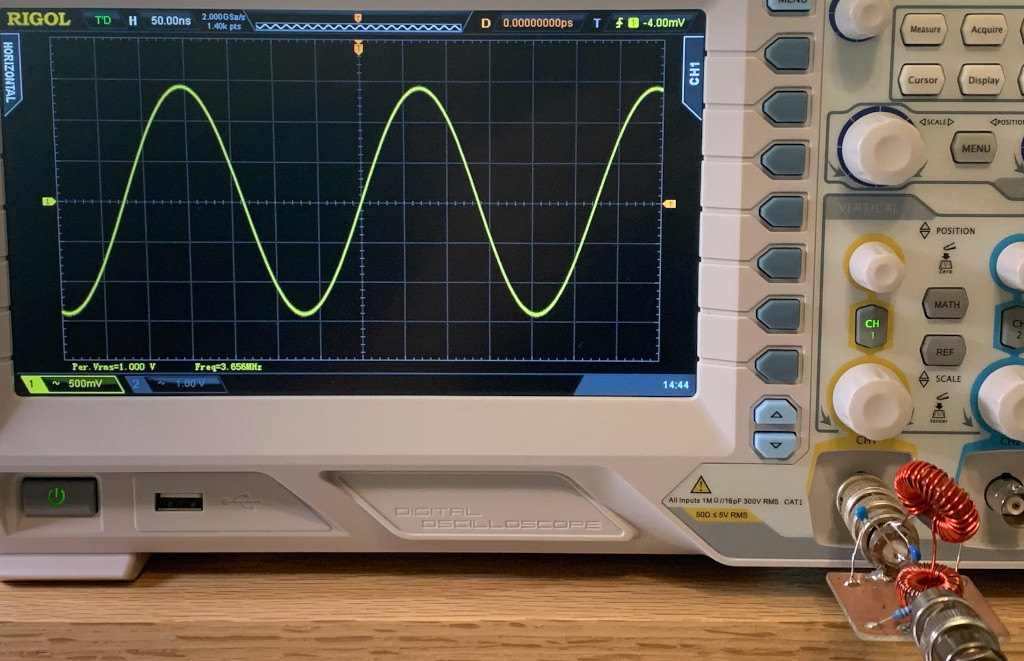
Oscilloscope Example
Previous Lab Notes
|
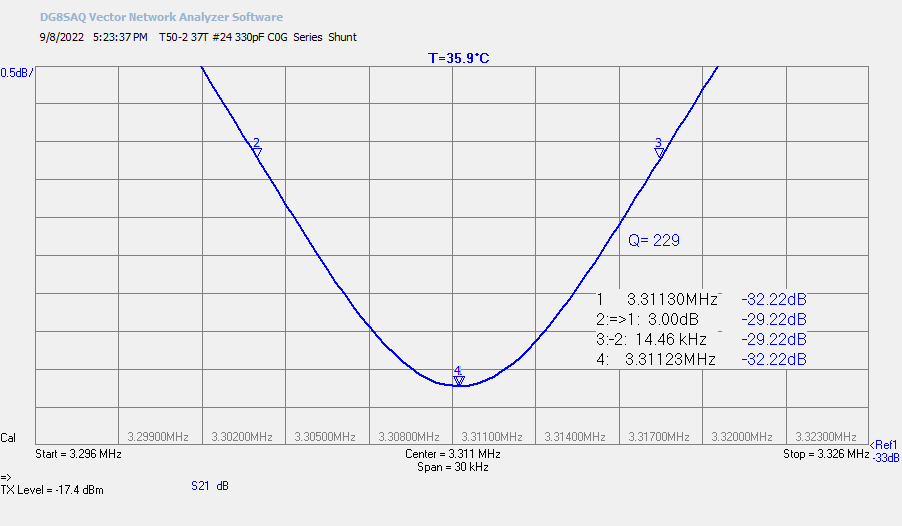
VNWA S21 Q Measurement
|
Injection Transformer Board
FT50-43 50:1 Turns
![]()
![]()
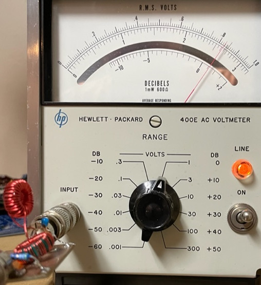
HP-400E Measurement Example
DUT = T50-2 37T #24 with 330pF C0G
Photos by Everett Sharp, N4CY
AWG set to 200mVrms at resonant frequency
Q = 250 * 0.83 = 208
VNWA Measured Q = 229
SimSmith Example
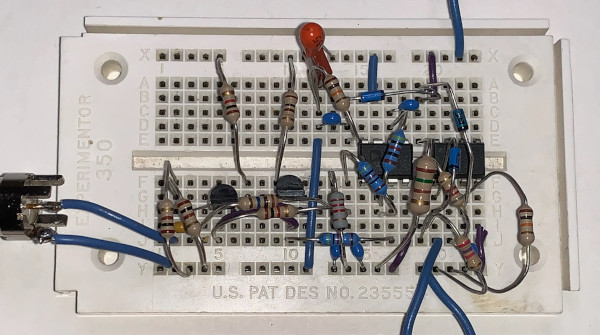
RF Voltmeter Prototype
Schematic
|
Prototype Breadboard
Q-Meter Prototype Schematic