FT114-43 Oscilloscope CMRR
Step 1: Calibrate Oscilloscope
Set Oscilloscope for 50Ω Input
Setup Signal Generator for 50Ω output at 14MHz.
Connect 50Ω Oscilloscope input to Signal generator
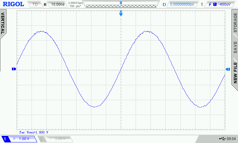
Adjust Signal generator output for, example, 1.8Vrms at Oscilloscope
Oscilloscope measuring 1.8Vrms calibration voltage
Step 2: Measure Common Mode Voltage
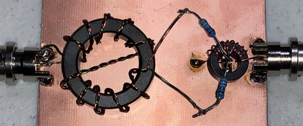
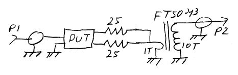
Place DUT Balun onto CMRR Test Fixture
Connect Signal generator to Fixture P1 and Oscilloscope to P2
Adjust Oscilloscope sensitivity for measurement
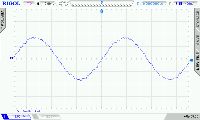
Oscilloscope measuring 2.345mVrms common mode voltage
Step 3: Compute CMRR
Compute dB for 1.8Vrms Input and 2.345mVrms common mode voltage
20 x Log10(1.8V/2.345mV) = 57.7dB
Subtract Fixture 10x current transformer, 20dB
57.7 - 20 = 37.7dB CMRR
Step 4: Compute Balun Choke Impedance
Compute Common Mode Current
2.345mV / 50Ω = 0.0467mA
Remove Fixture 10X current transformer, 0.0467mA x 10 = 0.467mA
Compute Choke Impedance as (V/2) / Current
(1.8 / 2) / 0.467mA = 1927Ω
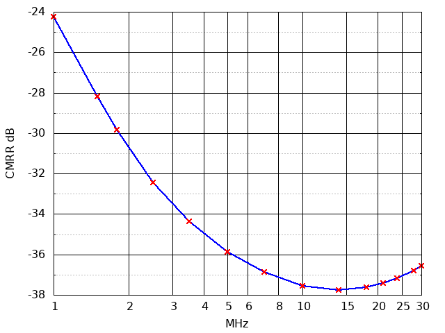
Step 5: Measure CMRR at Multiple Frequencies and Plot
Measure at several frequencies
Frequency
MHz
Common Mode
Vrms
1
11.05
1.5
7.02
1.8
5.8
2.5
4.3
3.5
3.44
5
2.9
7
2.58
10
2.39
14
2.33
18
2.37
21
2.42
24
2.49
28
2.6
30
2.67
Plot Data
gnuplot CMRR equation "(20 * log10(($2/1000)/1.8) + 20)"
Frequency versus CMRR