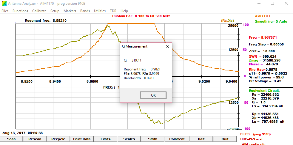
Measuring Q using SWR technique discussed in "Q Factor Measurements on L-C Circuits" by Jacques Audet, VE2AZX
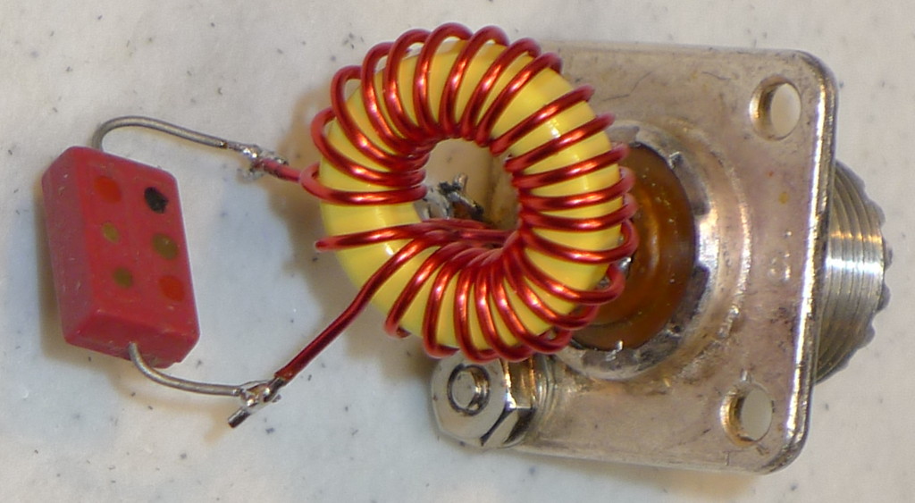
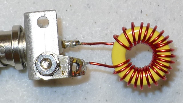
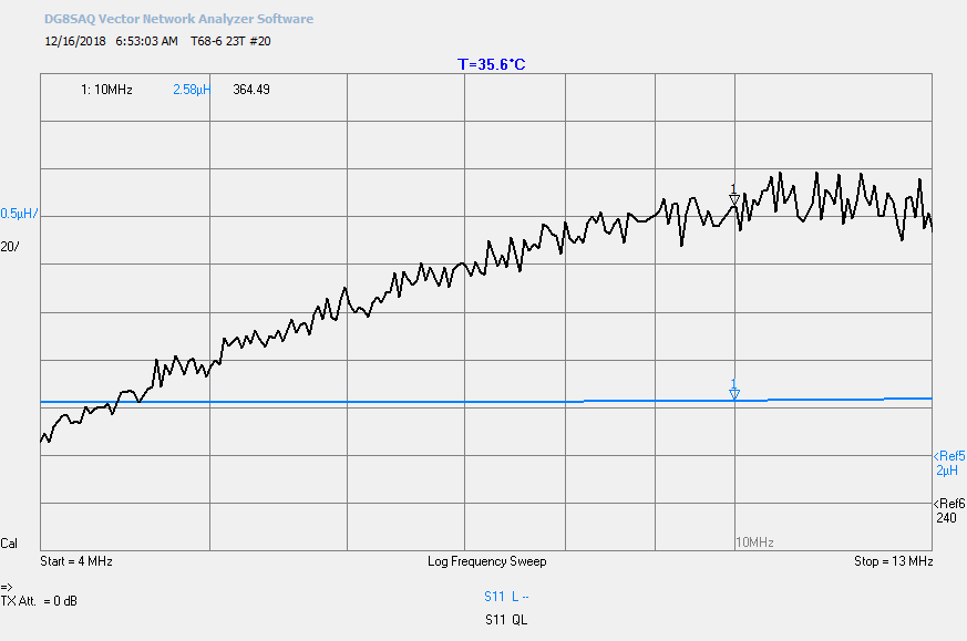
Measuring a T68-6 toroid with 23 turns #20 using the method shown in Figure 7 with a one turn Analyzer winding. One turn was selected for a reasonable impedance within the range of the VNA. Q is measured at 9 MHz using a 120 pF SM capacitor.
NOTE: Device pictures are presented resting on a bench. During measurements, always elevate device above the bench and avoid surrounding influences.
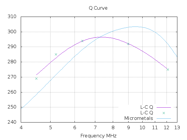
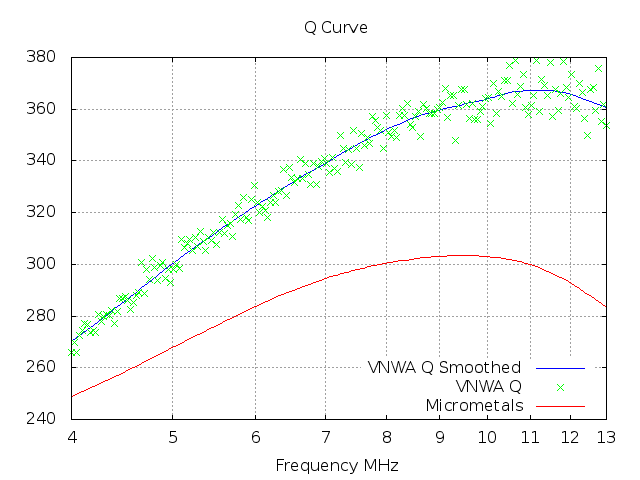
A Q curve for this device can be found on page 23 of " Q-Curves for Iron Powder Cores."
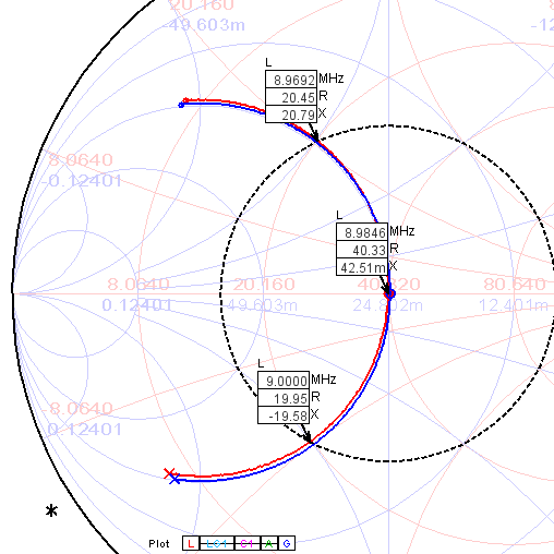
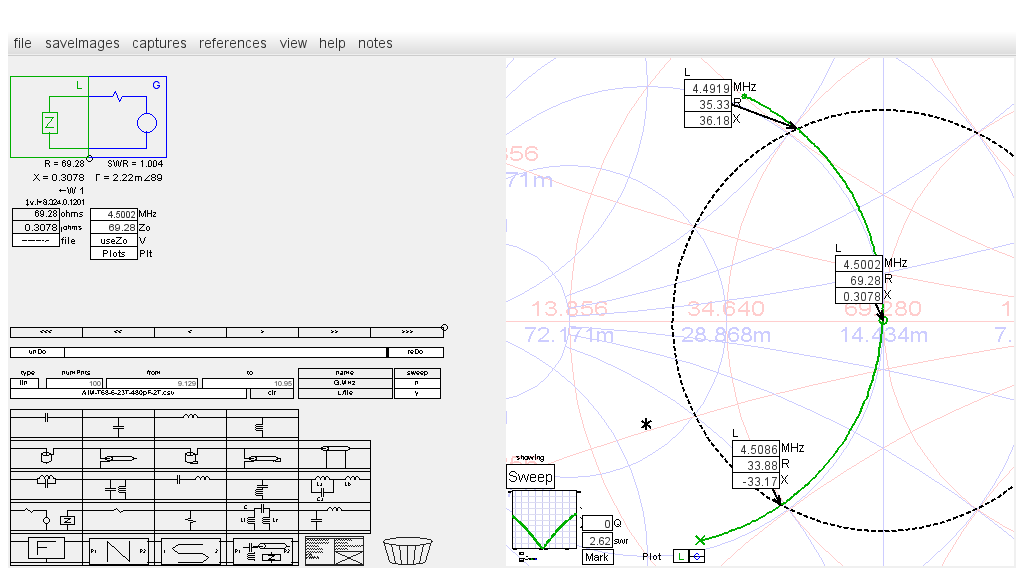
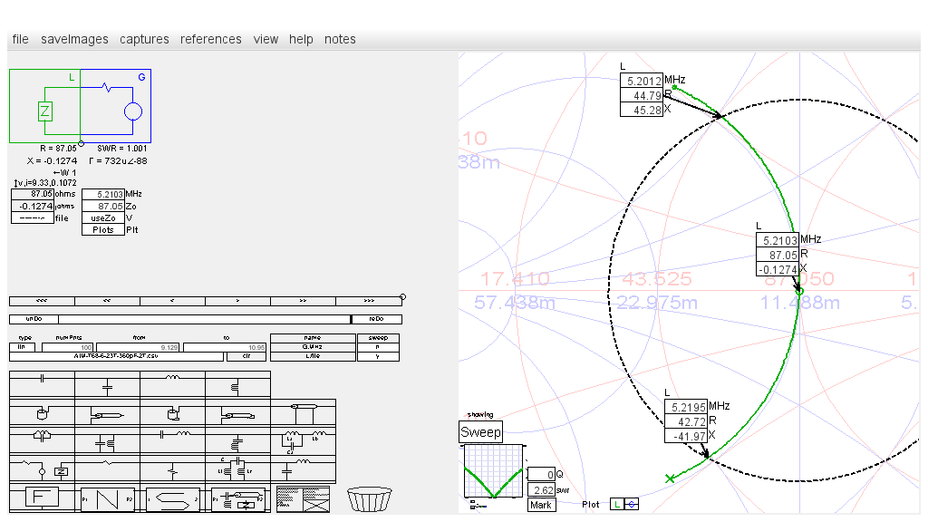
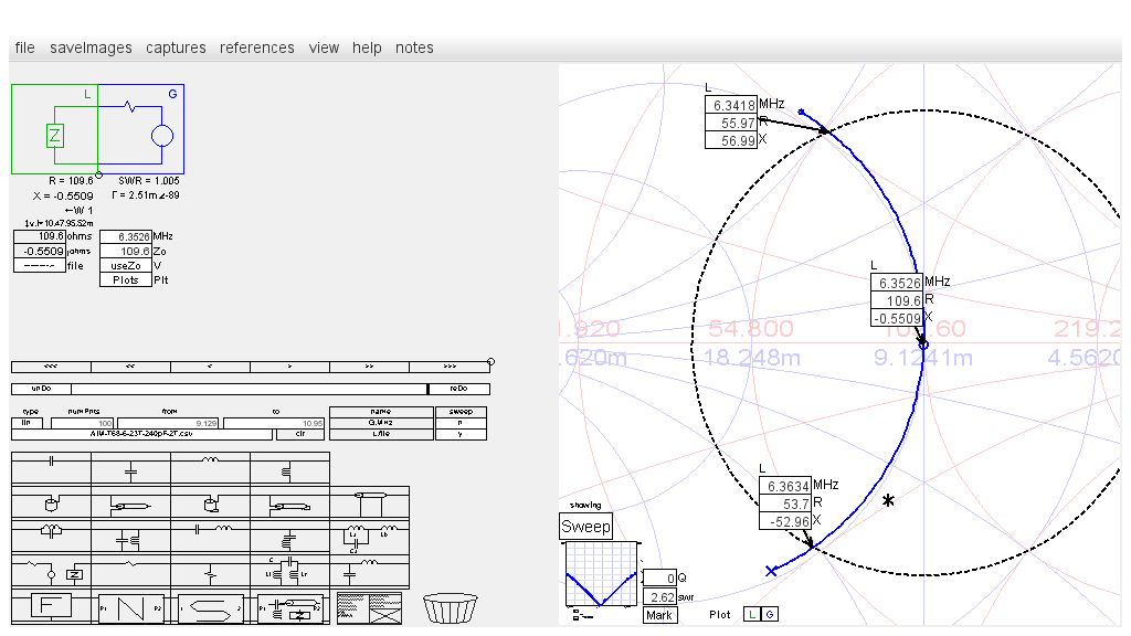
Resulting VNA scan file, AIM-T68-6-23T-120p.csv, is imported into the SimSmith Load block. SimSmith Smith chart SWR is set to 2.62, Zo is set for 1:1 SWR at resonance (40.32 Ohm), and markers are placed at the Sweep plot and SWR intersections.
L-C Q = 8.9846 / (9.0 - 8.9692) = 292
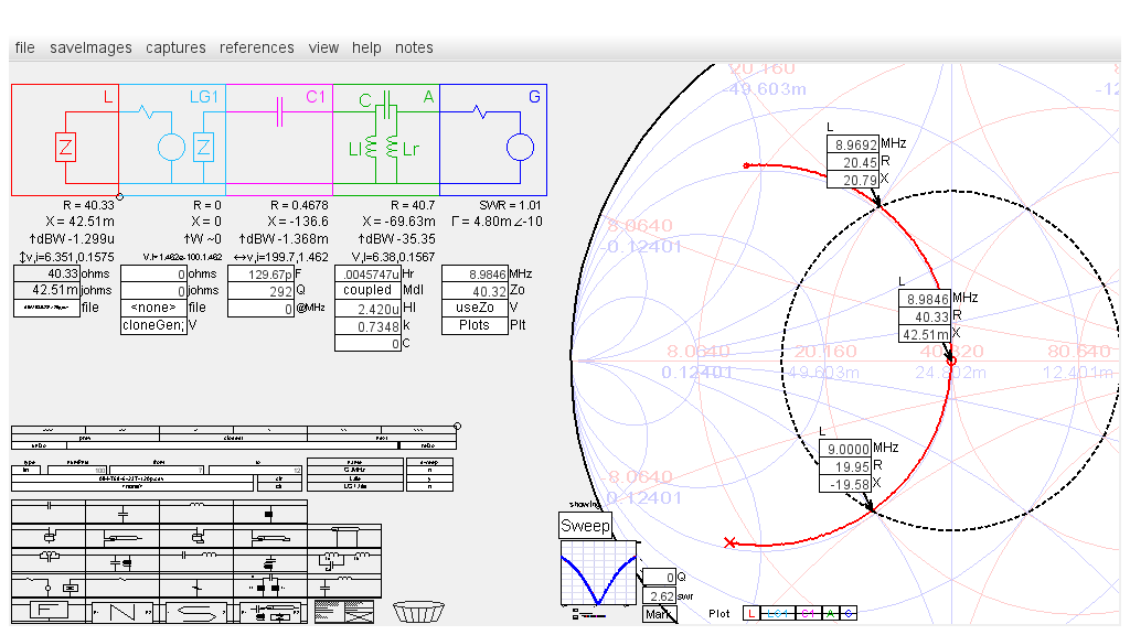
SimSmith blocks C1, A, and G model the test bench resonant L-C circuit with one turn winding. The capacitor block Q is set to 292. Transformer k and C is tuned for 1:1 SWR at resonant frequency. Notice near perfect match between the measured and modeled Sweep plots.
|
|